


Storage failures in utility field devices: What causes long-term reliability issues
A utility field device can pass qualification and still develop storage problems years later. This article explains the mechanisms behind...
We are here to help
Have a question or need guidance? Whether you’re searching for resources or want to connect with an expert, we’ve got you covered. Use the search bar on the right to find what you need.

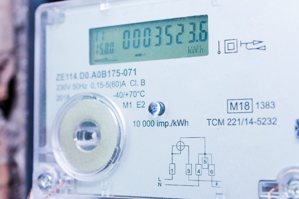
Utility field devices are often expected to operate for far longer than the development cycle used to design and qualify them. Smart meters, remote terminal units, grid-edge controllers, substation equipment, and other embedded systems may remain deployed for a decade or more while continuing to store configuration, measurements, counters, event history, diagnostic information, and firmware state. That creates a difficult validation problem. A credible utility device data integrity validation plan has to build lifecycle evidence. It must define what data needs to remain valid, model how storage will actually be used, represent meaningful aging and environmental stress, inject realistic faults, verify the recovered state, account for firmware evolution, and compare field behavior with the stress tests run during qualification.
In this context, “proving” long-term data integrity does not mean guaranteeing that every deployed device will preserve every byte for 20 years. It means demonstrating, with repeatable evidence, that defined integrity requirements are met within the tested workload, environmental, aging, firmware, and fault conditions. For the device-side storage technologies involved, see Tuxera smart energy solutions.
The device that matters is the one expected to exist years later, not the fresh prototype on the bench.
Data integrity is broader than asking whether a file can still be opened. A utility device may depend on several forms of persistent correctness at the same time. Measurement records may need the correct value, timestamp, and sequence. Configuration data may need to remain internally consistent after an unexpected restart. Firmware update state may need to identify an approved image and a valid recovery or rollback path. The storage structure itself also matters, since filesystem metadata, mappings, indexes, or database structures may need to remain valid enough for the application to recover and interpret the data correctly. A useful validation plan therefore considers content integrity, structural integrity, transactional integrity, sequencing and time relationships where required, retention over the defined period, compatibility across software versions, and the state available after recovery.
Security can support integrity where the system needs to detect or control unauthorized access and modification, but security and storage integrity are not interchangeable. Encryption or access control does not by itself demonstrate that a device can recover correct persistent state after media aging, power interruption, or an unsuccessful firmware transition. Before creating test cases, engineering teams first need to define what “correct” means for their devices.
A validation program becomes clearer when persistent information is divided into meaningful data classes. Configuration parameters may need to survive intense stress tests and remain internally consistent. Energy measurement data is usually the most critical class. Cumulative energy registers, interval load profiles, and billing snapshots must keep correct values, sequence, and timestamps for the full retention period, because utilities rely on them for invoicing and settlement. Depending on the meter design and the utility’s requirements, the device may also record event logs, such as power outages, tamper or cover-opening alarms, and disconnect operations, as well as power quality data, such as voltage sags, swells, and harmonic distortion. These logs often need a shorter retention window than billing data.
In PRIME-based smart metering deployments, where meter data is typically exchanged using the DLMS/COSEM data model, meters also commonly hold time-of-use tariff registers, maximum demand values, daily and monthly billing snapshots, instantaneous voltage and current values, and the meter clock state. Many meters buffer interval data and logs locally so that nothing is lost if the power line network or data concentrator is temporarily unavailable, and that buffered data must stay intact until the head-end system has collected and reconciled it. Calibration parameters, by contrast, may require the longest retention and the tightest controls on modification. Firmware and update state have different requirements again: the critical question may not be whether an old update log remains for 20 years, but whether an interrupted update leaves the endpoint in a known, approved state from which operation can continue or recover.
Not every piece of stored data needs 10 or 20 years of retention. The validation plan should define the required integrity behavior and retention period for each data class, and those requirements become the basis of the test protocol. Without them, a team can generate large amounts of validation data without establishing whether the device actually met the application requirement.
A practical lifecycle model runs define, model, age, stress, recover, verify, revalidate, monitor. Define the critical data and valid outcomes. Model the expected write workload, retention intervals, temperature exposure, storage utilization, power conditions, firmware changes, and other relevant lifecycle factors. Age the storage or device toward representative later-life conditions instead of relying exclusively on fresh media. Next, stress the system with realistic combinations of writes, temperature, utilization, power interruptions, and software activity. Exercise the recovery paths expected in deployed equipment. Verify the resulting state against a known expected result. Revalidate when software, media, workload, or storage assumptions materially change. Finally, compare field behavior with the assumptions made during qualification where the architecture exposes useful evidence. The value of this framework is that it treats long-term data integrity as a system property rather than a single flash memory specification or a one-time validation event.
A 10- or 20-year validation plan starts with an estimate of what the storage will actually experience. That includes application writes such as measurement records, event logs, counters, configuration changes, diagnostic information, and firmware updates, but the application workload may not represent the complete physical workload. Depending on the architecture, filesystems, flash-management layers, managed-storage controllers, metadata updates, garbage collection, wear leveling, mapping, and other housekeeping can create additional storage activity. The model should therefore consider what the application intends to write and what the persistence stack may need to do to maintain that data.
Temperature and storage utilization also belong in the lifecycle model. A new device operating under development-lab conditions can behave differently from the same device after years of writes, higher utilization, firmware changes, and exposure to its field thermal profile. Retention must be considered alongside endurance, because media specifications typically define retention and endurance under particular cycling and temperature conditions rather than as universal lifetime guarantees. The goal is not to predict every event a device will encounter. It is to create a model representative enough that the validation evidence is relevant to the intended deployment.
One of the strongest improvements an engineering team can make is to define valid outcomes before the fault occurs. Suppose a device is writing a new configuration and power is interrupted. After recovery, is the correct state the previous configuration, the new configuration, or either version as long as it is complete and internally consistent? The answer depends on the application. If that requirement is not defined in advance, a test may show that the device rebooted and the file was readable without demonstrating that the recovered state was actually valid. The same principle applies to counters, measurement sequences, databases, firmware state, and other persistent information.
An integrity invariant describes the property that must remain true. An update transaction might require that only an approved old or new image can become active. A record sequence might prohibit duplicates or impossible ordering. Configuration data might require dependent fields to remain mutually consistent. The validation question is not simply whether storage survived. It is whether the complete system recovered into one of the states the design defines as correct.
Endurance and retention are different engineering requirements, but long-lifecycle validation needs to consider how they interact. Endurance concerns repeated program and erase activity. Retention concerns whether written information remains recoverable for the required period under defined conditions. The test plan should therefore reflect the expected amount of cycling before a record must remain retained. A calibration parameter written infrequently but expected to remain valid for many years presents a different requirement from an operational log that is rewritten continuously and only needs short-term retention. Temperature further affects the analysis, since a device staying inside the component operating range does not automatically demonstrate that every data class will satisfy its required retention after the expected amount of cycling.
Development testing naturally begins with new hardware, but lifecycle validation cannot stop there. A fresh device generally has unused media, abundant working capacity, little accumulated wear, and no history of recovery events. Where appropriate, validation should also include representative higher-write states, reduced operating margin, high utilization, and relevant field temperature conditions. The objective is not to damage the media until it fails. It is to determine whether the device continues meeting its defined integrity, performance, and recovery requirements closer to the expected late-life condition. The mechanisms behind that late-life behavior are covered in storage failures in utility field devices.
Random power cycling can reveal useful problems, but targeted interruption often provides stronger validation evidence. Power-fail tests should exercise points where persistent state is actually changing. Depending on the device, that may include an application write, metadata update, configuration commit, log rotation, database transaction, firmware staging operation, startup sequence, or storage recovery. In a meter, power loss is a routine operating condition rather than a rare fault, because the device is powered from the same supply it measures. Tests should therefore include rapid repeated interruptions, such as auto-reclose sequences on the distribution network, and verify that power-fail detection and the available hold-up energy, for example from a supercapacitor, are still sufficient to commit critical registers at low temperature and with aged components.
Recovery itself deserves testing, because if the device is repairing or reconstructing persistent state after an interruption, a second interruption may exercise a different path from the original fault. Each test should have a known expected result. After recovery, engineers should verify which records exist, which configuration is active, whether sequences and counters remain valid, whether storage structures remain consistent, and whether the application can continue its expected operation. For meters, that also includes checking that the clock and timestamps remain correct after the outage and that the outage itself is recorded with its start and end times in the event log. The deeper mechanics of brownouts and interrupted meter writes belong in the related article on smart meter data loss after power events and brownouts; here the focus is lifecycle evidence.
A successful reboot is therefore useful but insufficient. A device might boot while silently reverting to older data, losing part of a transaction, reconstructing inconsistent application state, or requiring an unexpectedly long recovery period. Recovery criteria should be defined alongside integrity criteria, including any required readiness, storage-consistency, diagnostic, and timing requirements. There is no single acceptable recovery time for every device; it must come from the system design and from any applicable metrology requirements. For example, MID-approved electricity meters must keep the measured energy available for reading for at least 4 months after loss of supply, and must allow recovery of all measurement data present before a disturbance.
If a field device is expected to operate with relatively little free capacity later in life, validation should include representative high-utilization conditions rather than assuming storage will remain mostly empty. In some architectures, reduced working space can change garbage collection, relocation, latency, and write amplification, and whether those effects matter has to be demonstrated on the actual storage stack. In meters, load profiles and event logs are often fixed-size circular buffers, so utilization pressure more often comes from growing diagnostic logs, databases, and the space reserved for staging a full firmware image. Qualification programs often test variables separately because isolated tests are easier to design and diagnose, so a device may pass temperature, endurance, capacity, and power-interruption tests independently without demonstrating how it behaves when those conditions overlap.
A more representative scenario might combine aged or heavily written media, high utilization, elevated operating temperature, active logging, and a power interruption during a persistent transaction. The exact combination depends on the device and the failure mechanisms under evaluation. The objective is not to create the harshest possible test, which can introduce irrelevant failure modes, but to combine stresses that plausibly coexist in deployment.
A long-lived utility device may receive several firmware generations, and those changes can materially alter the storage workload even when the hardware is identical. New firmware may log more frequently, retain additional diagnostics, change checkpoint frequency, introduce database activity, stage larger updates, consume more persistent capacity, or alter the representation of existing data. This creates two validation questions. Does the new firmware still fit within the lifecycle workload model used to qualify the device? And does required persistent data remain valid and interpretable through the supported transition from old software to new software?
Where remote updates are supported, the plan should also exercise interruptions during relevant update stages and verify the expected recovery behavior. A validation result from the original firmware should not automatically be treated as permanent evidence for every later release. Revalidation is appropriate when a change materially affects an assumption or mechanism on which the previous result depended.
The device under test should not be the only authority deciding whether its data is correct. A validation rig should know what state was written and what state should exist after the test. Depending on the application and architecture, verification can use known test patterns, sequence numbers, expected-state models, readback comparison, hashes or checksums, metadata validation, and application-level consistency rules. Each method proves something different. A checksum can help detect whether a block of data changed, but it does not necessarily prove that the content represents the correct application state. Likewise, a filesystem reporting itself as mounted successfully does not demonstrate that a measurement sequence or configuration relationship is semantically correct. Independent verification should therefore be aligned with the integrity invariant being tested, and automation can improve quality assurance by injecting faults across many iterations, collecting actual results, comparing them with expected states, and retaining the evidence needed to investigate data integrity issues.
One passing device should not be treated as evidence of fleet-wide lifecycle behavior. Sample size, statistical confidence, acceleration methodology, test duration, and acceptance criteria depend on the device, storage technology, expected failure mechanism, program requirements, and applicable standards, and the validation plan should define these choices rather than importing an arbitrary sample number from another product. For electricity meters, the IEC 62059 dependability series, which includes accelerated reliability testing, is a useful reference point. Each test should also produce a repeatable validation record that identifies, at minimum, the device and software configuration, initial data state, workload or aging state, injected condition, expected result, actual result, and final disposition. That traceability becomes important when a field issue appears later or a firmware update requires revalidation, and structured records help teams distinguish a one-off laboratory anomaly from a repeatable integrity issue and compare results across firmware versions, media revisions, and test campaigns.
Lifecycle validation should continue to be tested against reality after deployment. Where the architecture provides useful information, periodic or continuous monitoring may reveal trends in storage utilization, corrected errors, recovery duration, temperature exposure, power events, reset history, firmware versions, write activity, or other health indicators. Not every storage system exposes the same telemetry, so monitoring requirements have to match the actual hardware and software stack. In AMI deployments, the head-end and meter data management systems already provide useful indicators, such as gaps in load profiles, duplicate or out-of-sequence intervals, unexpected clock corrections, and unusual reset or power-failure counts. Any additional storage-health telemetry has to be weighed against the limited bandwidth of narrowband networks such as PRIME power line communication.
Field failures are equally valuable. If maintenance teams encounter a storage-related problem that was not reproduced during development, the incident should be compared with the original lifecycle model, since the device may have experienced a workload, environmental condition, firmware pattern, or combined stress that qualification did not represent accurately. The loop runs from field evidence to revised assumptions to targeted reproduction to revalidation, and that feedback is more useful than treating validation as a document completed once before release. The operational side of the same question, keeping recoverable endpoint problems out of the field-service queue, is covered in reducing truck rolls with reliable embedded storage software for AMI.
Not every change requires repeating the entire program. Engineering teams should define triggers for reviewing previous evidence, such as changing storage media or controller, modifying the filesystem or flash-management layer, materially increasing write frequency, adding persistent logging, changing data structures, increasing expected utilization, altering firmware-update behavior, changing the thermal profile, or discovering a new field failure mode. A practical example in Europe is the move from 60-minute to 15-minute settlement periods, which can multiply load-profile writes by 4 on meters already in the field. The decision should rest on whether the change affects an assumption or mechanism that supported the previous result. A documented impact assessment can then determine whether targeted testing is sufficient or broader lifecycle revalidation is needed.
The storage software is one of the components under test, not a substitute for the test. In one smart meter customer project, lifespan testing of a platform built on Tuxera NitroFS and Tuxera FlashFX Tera simulated more than 20 years of product use and more than 1.2 billion SQLite3 database write transactions before the meter shipped. The useful principle is broader than the products: representative workload simulation can provide lifecycle evidence without waiting decades for calendar time to pass. Our webinar Why smart meters fail early, and what we can do about it walks through that project and the two failure mechanisms behind most early meter failures. The same validation applies to an MCU-class file system such as Tuxera EdgeFS, which is the more common fit for a meter. None of these components independently proves 10- or 20-year device integrity. Suitability has to be evaluated against the media, workload, platform, failure model, and system-level acceptance criteria.
Long-term utility device data integrity cannot be established from a fresh prototype running a short nominal test. The device that matters is the one expected to exist years later: after accumulated writes, firmware changes, environmental exposure, higher utilization, power interruptions, recovery cycles, and changes in the storage subsystem operating margin. A defensible utility device data integrity validation program therefore starts by defining the critical data and its required behavior. It models the intended lifecycle, represents meaningful aging and combined stress, injects faults at relevant boundaries, verifies the recovered state independently, reassesses significant firmware and storage changes, and uses field evidence to challenge the assumptions made during development.
That does not guarantee that every deployed device will preserve every record for 20 years. It provides something more technically useful: a repeatable body of evidence showing that the complete persistence system meets its defined integrity requirements within the lifecycle conditions it was designed and tested to handle.
RELATED ARTICLES

A utility field device can pass qualification and still develop storage problems years later. This article explains the mechanisms behind...
Selecting smart meter storage software means understanding how the complete persistence stack behaves across the product lifecycle. This 12-point checklist...
A smart meter can reboot, reconnect, and appear healthy while its most recent data is missing, stale, or inconsistent. This...

AMI keeps utility operations remote only while the endpoint stays recoverable and manageable. This article follows five persistence failure paths...
Suggested content for: